As outlined in Section 1 above, the calculation procedure falls naturally into two parts. The first deals with the subjects of radiation, dispersion and ignition and the second deals with the subject of heat transfer.These four subjects will be considered in detail under 2.2, 2.3, 2.4 and 2.5 respectively and the general concept will be discussed below.
Two adjacent tanks are considered.One is on fire and the flame is situated at tank top level and the radiation from it strikes the other tank where it is absorbed through the tank wall into the contents.This latter tank forms the target for the radiation and any stock will start to evaporate as the result of this heat input.The vapour forms a plume from the target tank top and this spreads downwind all the time being diluted by intrained air.Thus the vapour concentration passes through both the flammability limits and the vapour-air mixture within these limits will constitute a flammable plume.The boundary of this plume is defined by the contours where the concentration equals the lel.
Depending upon the intensity of radiation and the efficiency with which the energy is changed into vapourisation of the stock, a larger or smaller plume is obtained.Further, depending upon the wind conditions and the atmospheric stability, the flame from the tank on fire might be swept into the flammable plume or conversely the flammable plume might drift into the flame. In either case, ignition could possibly occur.If the radiation intensity is reduced by a change in the spacing between the tanks or the efficiency of heat conversion is altered by the use of insulation or water cooling then the intersection between flammable plume and flame can be prevented and ignition no longer occurs.
The flame is considered to form a cylinder having the same diameter as the taMe and having a height which is a function of that diameter and the wind speed. The flame is assumed to deflect at an angle to the horizontal when a wind is blowing and to form a distorted cylinder leaning in the downwind direction.This flame shape provides the basis for the source term in the radiation calculations since the flame temperature and flame emissivity are assumed fixed. The geometric shape of the flame can thus be specified by the slope of its axis (defined by the direction cosines), the centre of the top of the tank and the length of the flame.
Standard empirical relations (reference 1) are used to calculate the flame height and its deflection by the wind.The temperature of the flame is fixed at the constant value of 1500K and its emissivity is given the value of 0.3.
The portion of radiation incident on an element of the target tank from an element of the flame is a function of the distance between the two elements, the angle between the line joining the two elements and the normal to the plane of the receiving element and the angle between this same line and the normal to a plane containing the flame axis and the normal to the line.This portion of radiation is integrated over the flame surface and then repeated for each element of' surface over the entire surface of the tank exposed to radiation.The double integration evaluates the incident radiation
on the target tank from the flame taking into account the view factor associated with the specific orientation of flame and tank. This value is then modified by the appropriate value of the absorptivity of the tank surface which is assumed in the present calculation to be 0.9.The procedure is standard and can be obtained from any good reference work on radiative heat transfer.
The incident radiation flux to the target tank is a function of:
The dispersion of the flammable vapour is calculated using the usual Pasquil dispersion equation reference 2) for a neutrally buoyant plume from a finite contiguous source.The use of this equation is justified by the nature of the vapour release which normally consists of material which is heavier than air but which is at above ambient temperature and therefore at a reduced density. It is assumed that these two effects are self-compensating.Some allowance for the effect of reduced buoyancy with cooling of the vapour is included in the model by the use of the classical proportional relationship between the dispersion coefficients in the longitudinal and vertical directions with a proportionality constant of 5.
The variation of dispersion coefficients with distance from the source and as a function of atmospheric stability is assumed to take the form given in reference 2.
It is assumed that when the flammable plume boundary intersects with the flame boundary ignition will occur. It is thus necessary to define, in solid geometrical terms, these surfaces.Since both the plume boundary and the flame surface have been defined quite clearly in all three dimensions, a numerical technique has been developed to determine whether they intersect or not.
Although the equations and methods used in these calculations are quite standard the analysis used in this section has been put together specifically for the present application. Hence, considerably more detail is provided.
There are four aspects to the heat transfer calculation
Each mechanism has to be combined in an overall balance to determine the net rate of heat input to the liquid stock to produce vapour at its surface. Before looking at the individual mechanisms the overall balance is considered first.
Using algebraic notation so that direction of heat transfer as well as value is indicated:
| Heat from radiant source = | heat leaving in cooling water | (Q1) |
| + | ||
| heat to surrounding air | (Q2) | |
| + | ||
| heat to stock | (Q3) |
QT = Q1 + Q2 + Q3
Q1 = radiant heat absorbed + heat from tank - heat lost to surroundings
= Q11 + Qw - Q2
The cooling water enters at temperature Tc and leaves at temperature Th and the temperature rise is brought about by the heat absorbed
Q1 = F C (Th - Tc)
where F is the water flow rate and C is the specific heat of water.
Simple expressions involving heat transfer coefficients can be used to express the relationships which describe the various mechanisms of heat transfer
Q11 = h11 (Tw - T2) where Tw is the tank surface temperature
T2 = (Tc + Th) / 2
Q2 = h2 (T2 - Ta) where Ta is the air temperature
Q3 = hw (Tw - Twi)
= hi (Twi - Ti)
where Twi is the temperature of the inside of the tank wall and Ti is the temperature of the bulk of the stock.
The quantity of heat absorbed by the cooling water film as absorbed radiation is dependent upon the thickness of the water layer and the wavelength distribution of the intensity of the thermal radiation. At present there is no appropriate way in which this term can be evaluated from first principles. Hence, it is assumed that a small and constant proportion of the radiant energy may be absorbed and that
QW / QT = K0 (= constant which is much less than unity)
The equations can now be solved simultaneously to provide the relationship between
The expression is considerably simplified if some of the variables are grouped and where possible other terms are normalised to produce dimensionless terms.
The grouped variables are as follows
K1 = h2 / (2 F C)
K2 = 1 / (1 + K1 (1 + H11))
K3 = 1 / (1 / Hw + 1 / Hi)
The normalisations are as follows:
Temperature, t = T / (Ta - Tc)
Heat transfer coefficient H = h / h2
Heat fluxes q = Q / (h2 (Ta - Tc))
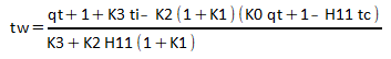
Then the relationship is:
q3 = K3 (tw - ti)
where
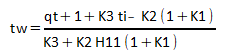
A variation of this equation is used when it is applied to the shadowed side of the tank which is not cooled:
q3 = K3 (tw - ti)
where
These relationships can be used in the appropriate combinations for the various parts of the tank (above and below the liquid level and on the fire and shadow sides) to provide the necessary connection between radiant heat input (qt) and heat available for evaporation (q3). Cooling water rate (contained in the term K1) and insulation thermal resistance (contained in the term K3) provide the other variables in the analysis.The minimum cooling water required to protect the tank from a known quantity of thermal radiation to prevent the evaporation of vapour at a rate related to the heat available for evaporation is obtained by numerical procedures.
The mechanism is that of convective heat transfer from a surface to a gas involving buoyant forces
Nu = 0.685 (Gr / 4)1/2
where:
Nu = h2 L / k = Nusselt Number
Gr = g b (To - Ta) L3 / v2 = Grasshoff Number
L is the characteristic dimension, the height, of the tank
k is the thermal conductivity of air
g is the acceleration constant
b is the thermal expansion coefficient of air
v is the kinematic viscosity of air.
The mechanism is well established and is similar to that obtaining in condensing films
Nu = 0.59 (Gr Pr)1/4 for 104 < (Gr Pr) <= 108
Nu = 0.13 (Gr Pr)1/3 for 108 < (Gr Pr)
where:
the Nusselt Number (Nu) is evaluated for the water film
the Grasshoff Number (Gr) is also evaluated for the water film
the Prandtl Number (Pr = C m / k) is also evaluated for the water film and m is the viscosity of water.
The mechanism is that of heat transfer from a solid surface to a liquid which is circulating under the forces of natural convection. In the present situation, the thermal gradient producing natural convection is dominated by the hot and cold sides of the tank. Such a mechanism can be quantified in terms of a heat transfer coefficient by the use of an equation very similar to that given in (ii) above but with a Grasshoff Number based on the thermal gradient from the hot side to the cold side of the tank.
Nu = 0.6 (Gr Pr)1/3
The same equation as given in (i) above is used with the appropriate properties for the vapour from the stock.